
前些剛好有一個血氧濃度的探頭,也不知道能不能使用,
便在網路上Google了一些使用Arduino量測血氧的文章,
有興趣可以參考:
- 網址:

https://cdn.instructables.com/F64/RVMI/I8PQWPMA/F64RVMII8PQWPMA.LARGE.jpg
於是依著網路上的說明,用洞洞板試了一個電路,很基礎地,放大電路,
但我將訊號用LabVIEW Interface for Arduino傳到PC上,
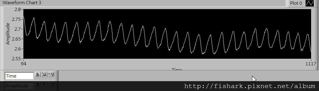
初步顯示的訊號如下,我加了一些Moving Average處理,
可以看到Red LEC的訊號
以及遠紅外LED的訊號
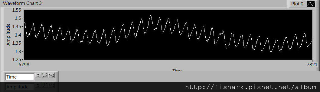
還滿有趣的,有時間想弄一個比較好的電路以及較好的訊號處理方式,
來試試看能不能有更好的波形。
其他網路關於Arduino的Oximeter資訊:
1.DIY Arduino Pulse Sensor (https://www.instructables.com/id/Simple-DIY-Pulse-Sensor/?ALLSTEPS)
文章作者: Jack
版權聲明: 本部落格所有文章除特別聲明外,均採用CC BY-NC-SA 4.0 授權協議。轉載請註明來源 X Workshop|量測自動化 × 嵌入式 × AI 開發實戰!
相關推薦
2022-01-15
[第13期]Use VS Code and PlatformIO to debug Arduino code in the ESP Wrover Kit with internal JTAG
This Video shows how to use VS Code and PlatformIO to debug Arduino code in the ESP Wrover Kit with internal JTAG. Introduce PlatformIO Introduce how to setup JTAG on ESP Wrover Kit and install JTAG Driver Install PlatformIO extension Setup PlatformIO Create new project and Debug Arduino Code 本影片說明如何使用VS Code and PlatformIO來偵錯Arduino程式在有內建JTAG的ESP Wrover Ki開發版上。 PlatformIO簡介 介紹如何設定與安裝JTAG驅動程式 安裝PlatformIO擴充 設定PlatformIO 建立與偵錯Arduino程式
2016-01-23
使用LabView for Arduino控制步進馬達(stepper motor)
LabVIEW for Arduino中有提供Stepper motor的範例, 我們配合實際的步進馬達與驅動電路板來作一個操作, 實際使用的狀況可以依所選的步進馬達種類(五線,四線,單極,雙極等),以及所一次需要控制幾個步進馬達,步進馬達所需要的電壓等,來做設定上的調配。 我就手上有的,四線式的步進馬達,選用L298N的驅動板,作一些測試, 打開LabVIEW for Arduino,選擇Arduino Stepper Motor.VI 在Block Diadram上作一些修改,包含COM port的設定,控制驅動電路路板是使用 Uno的10, 11, 12, 13數位腳位,4Wire等。 在設定值方面Set Speed指的是每秒走幾步(Steps per Second), # of Steps to Move指的是總共要走幾步,正值代表順時鐘,負值代表逆時鐘,Set Acceleration可以設定轉動的加速度會愈轉越快,設成0則是均速,然後按下Start Stepping即可驅動步進馬達轉動。另外也可以轉動Dial控制項,向右轉的話步進馬達也會向右轉,反之亦然。 附上...
2020-08-15
[Arduino] Edit Arduino code to control RGB LED in VS code/使用VS code編輯Arduino程式碼來控制RGB LED
This video show the blinking of RGB LED controlled by Mega2560. 本影片展示用Mega2560控制RGB LED閃爍的狀況。 Next video will express how to implement it by editing the Arduino code in the VS Code. 下一個影片將說明如何使用VS Code來編寫Arduino code來實現這樣的控制。 This video shows how to write the Arduino code of RGB LED blinking by using the VS code. 本部影片展示如何使用VS code去編輯控制RGB LED閃爍的Arduino程式碼。 Hardware: Mega2560 硬體: Mega2560 Steps: Use command “Arduino: Initialize” to create .ino file. Modify “c_cpp_properties.json” to add t...
2014-12-16
[Arduino與LabVIEW連結] LVH-LINX下載安裝
LabVIEW與Arduino的通訊一直是很受注意的部分,因為一般NI的DAQ卡價格不便宜, 如果是一般的Digital IO或是不需要太高速擷取的Analog signal,其實用Arduino就可以辦的到, 關於LabVIEW與Arduino的連結本來有有個LabVIEW Interface for Arduino Toolkit的, 不過這最近在NI的網頁上已經被置換成 “LINX - LVH” 可以參考這個網頁: https://sine.ni.com/nips/cds/view/p/lang/zht/nid/212478 按”下載”,會到https://www.ni.com/gate/gb/GB\_EVALTLKTLINXLVH/US 按照說明步驟,分下載步驟一的VIPM,和步驟二的LINX-LVH *Step One: Download and Install VI Package Manager (VIPM) *Step Two: Download LINX-LVH 先安裝好VIPM,然後再接者安裝LINX - LVH, 執行安裝LINX-LVH後會出現VIPM...
2015-07-07
Arduino Due 功能測試 (一) DAC Output
最近剛入手了Arduino Due,原因是因為是用Cortex-M3的MCU,想試一下這片板子的功能, 首先,來測是Due提供的DAC功能,分別有DAC0, DAC1兩個接腳可以使用, 經過一些搜尋,主要有幾點要注意: 1. You must use Arduino IDE 1.5 or later to program the Due–>要使用Arduino IDE 1.5以上的版本。 2. The microcontroller mounted on the Arduino Due runs at 3.3V, this means that you can power your sensors and drive your actuartors only with 3.3V. Connecting higher voltages, like the 5V commonly used with the other Arduino boards will damage the Due.–>使用3.3V,5V的電壓會傷害Due。 3.https://www.arduin...
2015-02-01
LabVIEW與藍芽模組HC-06的資料傳輸測試
拿到HC-06的藍芽模組後試了寫了一些程式,卻發現獻資料在傳輸時都是錯誤的資料, 於是只好從頭開始查起,我決定用PC端的LabVIEW用串列傳輸資料給USB/TTL模組, USB/TTL是使用USB接頭連接在PC上模擬一個COM Port,USB/TTL的另一端連接在HC-06藍芽模組上, 注意藍芽模組的電源不能超過HC-06的電源限制,USB/TTL Tx –>HC-06 Rx,USB/TTL Rx –>HC-06 Tx, PC端: LabVIEW的Advanced Serial Write and Read.vi, 接者要使用Android 手機端的APP來接收和傳送資料確定HC-06的功能是ok的, 我使用的App為: Bluetooth SPP(蓝牙串口助手) https://play.google.com/store/apps/details?id=mobi.dzs.android.BluetoothSPP&hl=zh_TW 藍牙串口 https://play.google.com/store...
公告
本站文章自痞客邦(2006–2024)搬家而來,舊文章的程式碼與圖片如有缺漏,歡迎留言告知。