目前剛學習STM32F4的使用,如果內容有些錯誤,日後發現會在進行修改,
在學習Micorchip的Port使用時,每個Port由8個pin組成,每個pin有多重功能,必須要先設定這個pin是digital或analog,然設設定是input還是output,
在學習STM32F4時也是一樣,每個pin有多重功能,想要使用哪個pin做甚麼事,必須要做事先的設定,
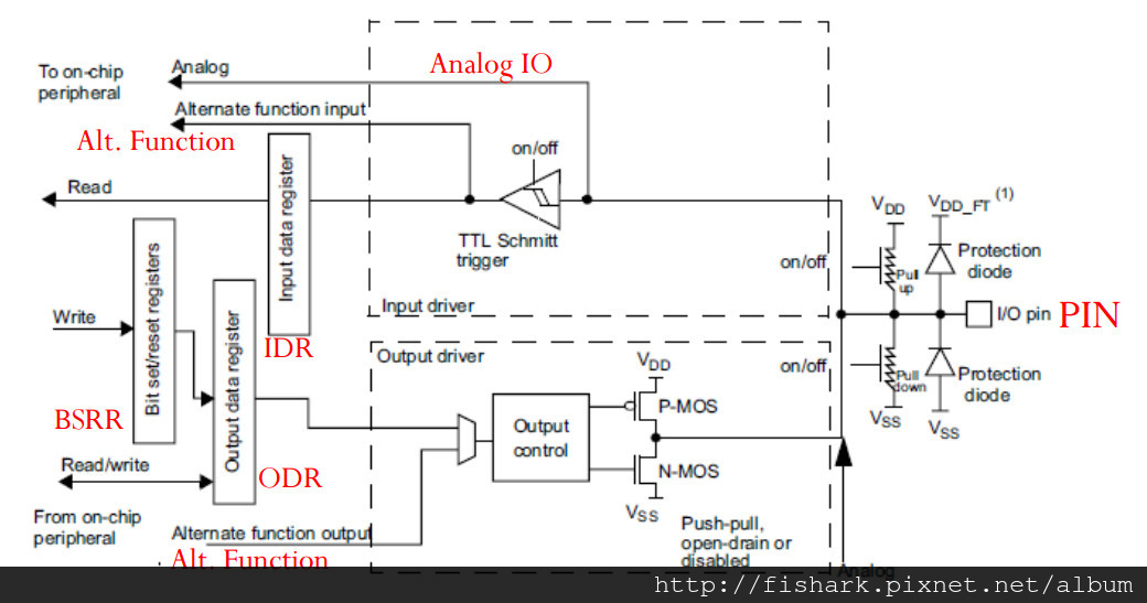
STM32F4 GPIO的主要配置,可以設定不同的功能(可以比對下面的功能方塊圖):
- 輸入浮接 (Input floating)
- 輸入上拉 (Input pull-up)
- 輸入下拉 (Input-pull-down)
- 類比輸入 (Analog)
- 開漏輸出 (Output open-drain)
- 推挽輸出 (Output push-pull)
- 推挽式交替功能 (Alternate function push-pull)
- 開漏式交替功能 (Alternate function open-drain)
這些功能可以直接設定相關的暫存器,也用函數來設定,但必須include相關的H檔,如:
1
2
3
4
5
| #include "STM32F4xx_GPIO.h" --> General Purpose Input Output
#include "STM32F4xx_RCC.h" --> Reset and Clock Control
相關函數:
|
1
2
3
4
5
6
7
8
9
10
11
12
| GPIO_InitTypeDef GPIO_InitStructure;
RCC_AHB1PeriphClockCmd(RCC_AHB1Periph_GPIOG, ENABLE); --> 開啟GPIO時脈
GPIO_InitStructure.GPIO_Pin = GPIO_Pin_13 | GPIO_Pin_14; --> 設定要控制腳位位置
GPIO_InitStructure.GPIO_Mode = GPIO_Mode_OUT; --> 設定所需要的模式,如Digital input, output
GPIO_InitStructure.GPIO_OType = GPIO_OType_PP; --> 設定MOS transsitor配置
GPIO_InitStructure.GPIO_Speed = GPIO_Speed_100MHz; --> 設定速度or頻率
GPIO_InitStructure.GPIO_PuPd = GPIO_PuPd_NOPULL; --> 設定電阻配置
GPIO_Init(GPIOG, &GPIO_InitStructure); --> 進行GPIO結構註冊
|
1
| GPIO中對數位腳位讀寫的暫存器為IDR(輸入),ODR(輸出),BSRR為設定與清除。
|
1
2
3
4
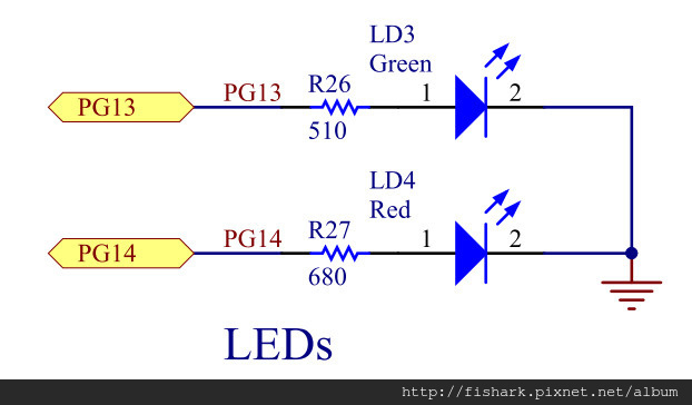
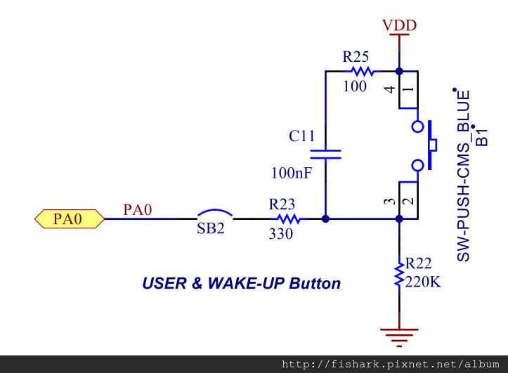
| 以下為使用按鈕來啟動LED範例,同時Demo Digiral input與output功能,
先看一下電路圖:
(1) LED -->PG13,14
|
(2) 按鈕(stwich) –>PA0
範例程式為:
1
2
3
4
5
6
7
8
9
10
11
12
13
14
15
16
17
18
19
20
21
22
23
24
25
26
27
28
29
30
31
32
33
34
35
36
37
38
39
40
41
42
43
44
45
46
47
48
49
50
51
| #include "STM32F4xx.h"
#include "STM32F4xx_GPIO.h"
#include "STM32F4xx_RCC.h"
void LED_GPIO_Config(void)
{
GPIO_InitTypeDef GPIO_InitStructure;
RCC_AHB1PeriphClockCmd(RCC_AHB1Periph_GPIOG, ENABLE);
GPIO_InitStructure.GPIO_Pin = GPIO_Pin_13 | GPIO_Pin_14;
GPIO_InitStructure.GPIO_Mode = GPIO_Mode_OUT;
GPIO_InitStructure.GPIO_OType = GPIO_OType_PP;
GPIO_InitStructure.GPIO_Speed = GPIO_Speed_100MHz;
GPIO_InitStructure.GPIO_PuPd = GPIO_PuPd_NOPULL;
GPIO_Init(GPIOG, &GPIO_InitStructure);
}
void Switch_Init (void)
{
GPIO_InitTypeDef GPIO_InitStructure;
RCC_AHB1PeriphClockCmd(RCC_AHB1Periph_GPIOA, ENABLE);
GPIO_InitStructure.GPIO_Pin = GPIO_Pin_0;
GPIO_InitStructure.GPIO_Mode = GPIO_Mode_IN;
GPIO_InitStructure.GPIO_PuPd = GPIO_PuPd_DOWN;
GPIO_Init(GPIOA, &GPIO_InitStructure);
}
void main(void)
{
char switches = 0;
LED_GPIO_Config();
Switch_Init();
while(1)
{
switches = GPIOA->IDR;
if (switches & (uint32_t)0x00000001)
{
GPIOG->BSRRL = GPIO_Pin_13;
GPIOG->BSRRL = GPIO_Pin_14;
}
else
{
GPIOG->BSRRH = GPIO_Pin_13;
GPIOG->BSRRH = GPIO_Pin_14;
}
};
}
|