這一個範例是說明如何使用Mega2560與MCP23018作I2C通訊,
MCP23018為一個16通道的IO擴充IC,可以一口氣增加16個Digtal input 與 output,
在使用Arduino的通訊協定時,我們會用到Wire的函式庫,所以一開始要將Wire.h include進來,
我參考了一些網站來撰寫這個範例:
https://github.com/maniacbug/Arduino/blob/master/Double\_Seven\_LED\_Test/Double\_Seven\_LED\_Test.pde
https://byterule.com/2013/8/21/i2c-arduino-to-mcp-23018.aspx
https://www.arduino.cc/en/reference/wire
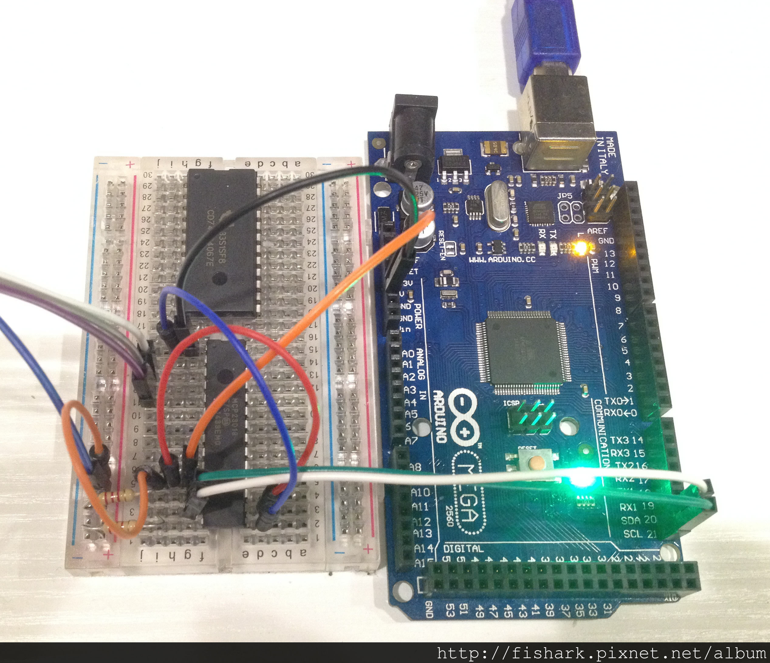
基本的接腳為:
MCP23018/Arduino
Addr -> gnd (gets mcpaddr for wire of 0x20)
Reset-> V+
VSS -> gnd
Vdd -> v+
SDA-> 20 W/pullup resistor 1.5K+
SCL -> 21 W/pullup resistor 1.5K+
GPB0–> LED G
GPB1–> LED B
GPB2–> LED R
Arduino code為:
1 2 3 4 5 6 7 8 9 10 11 12 13 14 15 16 17 18 19 20 21 22 23 24 25 26 27 28 29 30 31 32 33 34 35 36 37 38 39 40 41 42 43 44 45 46 47 48 49 50 51 52 53 54 #include <Wire.h> const uint8_t I2C_MCP23018 = B0100000;const uint8_t IODIRA = 0x0 ;const uint8_t IODIRB = 0x1 ;const uint8_t IOCON = 0xA ;const uint8_t IOCON_SEQOP[] = { IOCON, 5 };const uint8_t GPPUA = 0x0C ;const uint8_t GPPUB = 0x0D ;const uint8_t GPIOA = 0x12 ;const uint8_t GPIOB = 0x13 ;const uint8_t OLATA = 0x14 ;const uint8_t OLATB = 0x15 ;void setup () Serial .begin (9600 ); delay (2000 ); Wire .begin (); Wire .beginTransmission (I2C_MCP23018); Wire .write (IODIRA); Wire .write (0x00 ); Wire .write (0x00 ); Wire .endTransmission (); } void loop () Wire .beginTransmission (I2C_MCP23018); Wire .write (GPIOA); Wire .write (0xff ); Wire .write (B00000001); Wire .endTransmission (); delay (1000 ); Wire .beginTransmission (I2C_MCP23018); Wire .write (GPIOA); Wire .write (0xff ); Wire .write (B00000010); Wire .endTransmission (); delay (1000 ); Wire .beginTransmission (I2C_MCP23018); Wire .write (GPIOA); Wire .write (0xff ); Wire .write (B00000100); Wire .endTransmission (); delay (1000 ); }
Mega2560與MCP23018接線狀況:
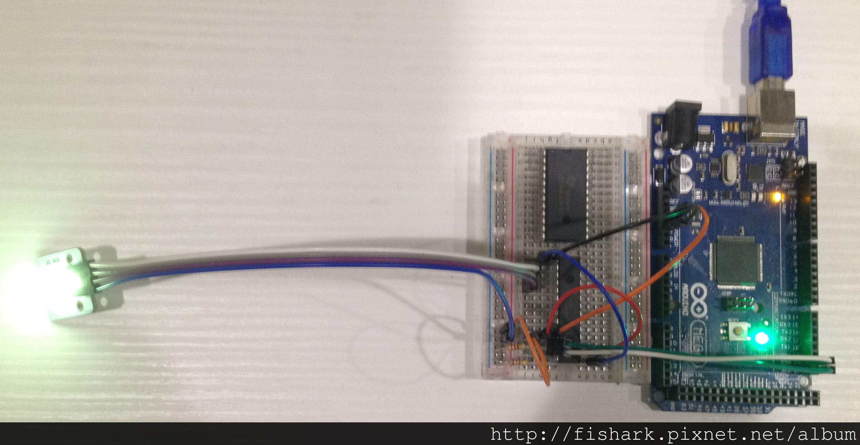
RGB LED的控制狀況: 紅,綠,藍顏色會每一秒做一次變化。
VIDEO